This manual details the proper installation of the xnx xnx Transmitter, ensuring optimal performance and longevity. Careful adherence to these guidelines is crucial.
What is the xnx xnx Transmitter?
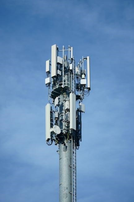
The xnx xnx Transmitter is a sophisticated radio frequency device designed for reliable and long-range communication. It functions by converting electrical signals into radio waves, transmitting data across considerable distances.
This transmitter is engineered for diverse applications, including broadcasting, telemetry, and data transfer. Its robust design ensures stable operation even in challenging environmental conditions. Understanding its core functionality is paramount for successful installation and operation. The device utilizes advanced modulation techniques for efficient signal transmission and minimal interference.
Key Features and Specifications
The xnx xnx Transmitter boasts several key features, including adjustable power output, multiple operating frequencies, and a durable, weather-resistant enclosure. It supports various modulation schemes for optimized signal quality.
Specifications: Frequency Range: 100-500 MHz; Power Output: 1-10 Watts; Operating Voltage: 12-24 VDC; Antenna Impedance: 50 Ohms; Operating Temperature: -20°C to +60°C. These specifications ensure compatibility and reliable performance across a wide range of applications and environments. Detailed technical specifications are found in the appendix.
Unboxing and Component Check
Carefully unpack the xnx xnx Transmitter and verify all listed components are present and undamaged before proceeding with installation.
Package Contents List
Upon opening the package, please ensure the following items are included: One (1) xnx xnx Transmitter unit, one (1) high-gain antenna, one (1) power adapter with appropriate regional plug, one (1) antenna connection cable (typically RG-58 or equivalent), a mounting bracket kit complete with screws and bolts, and this comprehensive installation manual.
Additionally, you should find a quick start guide for basic setup, a bag containing necessary grounding hardware, and a set of cable ties for neat organization. If any items are missing or appear damaged, immediately contact customer support for assistance and do not attempt installation.
Identifying the Components
The xnx xnx Transmitter unit features a robust metal casing with clearly labeled ports for antenna connection, power input, and a configuration interface (typically USB or Ethernet). The included antenna is directional; note the arrow indicating its primary radiation pattern.
The mounting bracket consists of adjustable arms and a base plate designed for secure attachment to various surfaces. The power adapter displays input voltage and output amperage. Familiarize yourself with each component’s function before proceeding; diagrams are provided within this manual for visual reference.
Safety Precautions
Always disconnect power before working on the xnx xnx Transmitter. Observe all warnings and follow guidelines to prevent injury or equipment damage.
General Safety Guidelines
Prior to installation, thoroughly read and understand this entire manual. Qualified personnel should perform all installation and maintenance procedures. Wear appropriate personal protective equipment (PPE), including safety glasses and gloves. Ensure the work area is clean, dry, and well-lit.
Never attempt to modify the xnx xnx Transmitter without explicit authorization. Avoid working during inclement weather. Be mindful of potential trip hazards and secure all cabling appropriately. Regularly inspect all connections for tightness and damage. Report any unusual conditions immediately. Failure to follow these guidelines could result in personal injury or equipment malfunction.
RF Radiation Safety
The xnx xnx Transmitter emits radio frequency (RF) energy. Maintain a safe distance from the antenna during operation – a minimum of [insert distance] is recommended. Avoid prolonged exposure to RF fields. Individuals with medical implants (pacemakers, etc.) should consult their physician before working near the transmitter.
Ensure the antenna is properly grounded to minimize RF leakage. Regularly monitor RF radiation levels using appropriate testing equipment. Adhere to all applicable regulatory limits for RF exposure. Never operate the transmitter with a damaged antenna or cable. Prioritize safety and responsible operation at all times.
Installation Preparation
Before commencing, thoroughly plan the installation site and gather all necessary tools for a smooth and efficient setup process.
Site Selection Considerations
Choosing the correct location is paramount for optimal transmitter performance. Prioritize a site with a clear line of sight to the intended reception area, minimizing obstructions like buildings or dense foliage.
Elevation is beneficial, providing increased range. Ensure the location offers adequate protection from the elements – rain, snow, and direct sunlight can impact performance and longevity.
Consider accessibility for maintenance and future upgrades. Avoid areas prone to interference from other electronic devices or sources of electromagnetic noise. A stable, level surface is essential for secure mounting. Finally, verify local regulations regarding antenna height and placement.
Tools Required for Installation
Proper installation necessitates having the correct tools readily available. You will need a calibrated torque wrench for secure connections, preventing damage to components. A set of adjustable wrenches and screwdrivers (Phillips and flathead) are essential for various fasteners.
An antenna alignment tool ensures precise positioning for optimal signal transmission. A cable cutter and crimper are required for preparing and connecting antenna cables. Safety glasses and gloves are crucial for personal protection.
A multimeter is needed for electrical testing, and a grounding kit verifies proper grounding. Finally, a level ensures the transmitter unit is mounted securely and stably.
Mounting the Transmitter
Securely mounting the xnx xnx Transmitter is vital for stable operation. Follow these steps to ensure proper alignment and prevent potential damage or interference.
Antenna Mounting Procedures
Proper antenna mounting significantly impacts transmission range and signal clarity. Begin by selecting a mounting location clear of obstructions like trees and buildings. Use the provided mounting bracket, ensuring it’s securely fastened to a stable structure – a mast or sturdy pole is recommended.
Orient the antenna according to the signal propagation requirements, typically vertically for omnidirectional coverage. Tighten all connections firmly, but avoid over-tightening which could damage the antenna or bracket. Double-check the antenna’s grounding to protect against lightning strikes and static buildup. Regularly inspect the mount for corrosion or looseness.
Transmitter Unit Mounting
Securely mounting the transmitter unit protects it from environmental factors and physical damage. Choose a sheltered location, away from direct sunlight, rain, and excessive heat. Utilize the provided mounting plate and hardware, attaching it to a solid surface like a wall or rack.
Ensure adequate ventilation around the unit to prevent overheating. Avoid mounting near strong electromagnetic interference sources. Confirm the mounting allows easy access for maintenance and inspections. Double-check all screws and fasteners are tightened appropriately, preventing vibration-related issues. Proper mounting extends the transmitter’s lifespan.
Electrical Connections
Establishing correct electrical connections is vital for safe and reliable operation. Always disconnect power before wiring, and verify voltage compatibility carefully.
Power Supply Requirements
The xnx xnx Transmitter operates on a 12-24V DC power supply, with a recommended amperage of at least 5A. Utilizing a power supply outside of these specifications may result in damage to the unit or suboptimal performance.
Ensure the power supply is adequately rated to handle potential peak current draws, especially during transmission bursts. A regulated power supply is strongly advised to maintain a stable voltage, preventing fluctuations that could affect signal quality.
Polarity must be strictly observed – positive to positive and negative to negative – as reversed polarity will immediately void the warranty and likely damage the transmitter. Consider using a surge protector for added safety.
Grounding Instructions
Proper grounding is essential for safety and optimal performance of the xnx xnx Transmitter. Connect the transmitter’s grounding lug to a known, reliable earth ground using a heavy-gauge wire (minimum 10 AWG).
This grounding connection minimizes the risk of electrical shock and reduces potential interference from external sources. Avoid using gas pipes or water pipes as grounding points, as these can be unreliable or create hazardous conditions.
A dedicated grounding rod driven into the earth is the preferred method. Regularly inspect the grounding connection for corrosion or looseness, ensuring a secure and effective ground path is maintained at all times.
Antenna Connections
Securely connect the antenna cable to the transmitter, ensuring a weatherproof seal. Proper antenna connection maximizes signal transmission and minimizes signal loss.
Connecting the Antenna Cable
Begin by ensuring the transmitter is powered off before connecting any cables. Carefully inspect the antenna cable and connector for any signs of damage, such as fraying or corrosion. Use a suitable coaxial cable specifically designed for the transmitter’s frequency range.
Align the connector with the transmitter’s antenna port and gently tighten it by hand – avoid over-tightening, which can damage the port. Once connected, visually inspect the connection to confirm it’s secure and properly seated. A loose connection will significantly degrade performance.
Remember to use appropriate weatherproofing sealant around the connection point if the antenna is exposed to the elements.
SWR (Standing Wave Ratio) Measurement
After connecting the antenna cable, measuring the SWR is critical for optimal transmitter performance and protection. A high SWR indicates impedance mismatch, potentially damaging the transmitter. Utilize an SWR meter connected between the transmitter and the antenna cable.
Power on the transmitter at a low power setting. Observe the SWR reading across the desired frequency range. An ideal SWR is 1:1, but readings below 2:1 are generally acceptable. If the SWR is excessively high, immediately power off the transmitter and re-examine the antenna connection and cable.
Adjust the antenna or cable length to minimize the SWR before operating at full power.
Configuration and Programming
Proper configuration unlocks the xnx xnx Transmitter’s full potential. This section guides you through accessing settings and customizing transmission parameters effectively.
Accessing the Configuration Interface
The xnx xnx Transmitter’s configuration is accessed via a dedicated web interface. Ensure the transmitter is powered on and connected to your network using an Ethernet cable. Locate the transmitter’s IP address, typically found on a sticker affixed to the unit or through your network’s DHCP server.
Open a web browser on a computer connected to the same network and enter the IP address into the address bar. You will be prompted for login credentials – the default username is ‘admin’ and the default password is ‘password’. It is strongly recommended to change these default credentials immediately for security reasons. Once logged in, you’ll have access to all configuration options.
Setting Transmission Parameters
Within the configuration interface, navigate to the ‘Transmission’ settings. Here, you can adjust crucial parameters for optimal performance. Power output levels are adjustable, ranging from low power for short-range applications to high power for extended coverage – be mindful of regulatory limits!
You can also configure the data rate, selecting from available options to balance speed and reliability. Modulation schemes (e.g., QPSK, 16QAM) can be chosen based on your specific needs. Always test changes in a controlled environment before full deployment to ensure stable and efficient transmission.
Frequency Selection and Channel Assignment
Carefully select an operating frequency within the permitted spectrum. The xnx xnx Transmitter supports a range of frequencies; consult local regulations for authorized bands. Avoid frequencies known to experience interference. Channel assignment is critical for minimizing collisions with other devices.
Utilize the channel scan feature to identify clear channels. Manually assign a channel if automatic selection proves unreliable. Document your chosen frequency and channel for future reference and troubleshooting. Incorrect settings can lead to poor performance or legal violations.
Testing and Verification
Post-installation, thorough testing confirms correct operation. Verify signal transmission, range, and clarity to ensure the xnx xnx Transmitter functions as expected.
Initial Power-Up Test
Before commencing full operation, perform a crucial initial power-up test. Connect the power supply, ensuring correct voltage and polarity as specified in the electrical requirements section. Observe the transmitter’s indicator lights; a steady power indicator confirms successful connection.
Listen for any unusual noises emanating from the unit. If everything appears normal, briefly transmit a test signal at a low power setting. Monitor the signal on a compatible receiver to verify transmission. Document the results of this initial test for future reference, noting any anomalies immediately.
Range and Signal Strength Testing
Following the initial power-up, rigorously test the transmitter’s range and signal strength. Utilize a calibrated receiver and antenna setup at various distances from the transmitter. Record signal strength readings at predetermined intervals – 100ft, 500ft, 1000ft, and beyond, if feasible.
Compare these readings against expected values based on transmitter power and antenna specifications. Note any significant signal degradation or dropouts. Environmental factors like obstructions can impact results; document these conditions alongside your measurements for accurate analysis.

Troubleshooting Common Issues
This section provides solutions for frequently encountered problems with the xnx xnx Transmitter, aiding in swift diagnosis and effective resolution.
No Power to the Transmitter
If the xnx xnx Transmitter fails to power on, begin by verifying the power source. Ensure the power cable is securely connected to both the transmitter and a functioning electrical outlet. Check the circuit breaker or fuse associated with the outlet to confirm it hasn’t tripped or blown.
Next, inspect the transmitter’s power switch; confirm it’s in the ‘on’ position. Utilize a multimeter to test the voltage at the power input of the transmitter, ensuring it matches the specified requirements; If voltage is present but the unit remains unresponsive, a potential internal fault may exist, requiring professional servicing.
Weak Signal Output
A weak signal from the xnx xnx Transmitter can stem from several issues. First, meticulously re-examine the antenna connection – ensure it’s tight and free from corrosion. Verify the antenna cable isn’t damaged or kinked, as this significantly impacts signal transmission.
Confirm the correct frequency and power settings are configured within the transmitter’s interface. Check for obstructions between the transmitter and the intended receiver. Finally, perform an SWR measurement; a high SWR indicates an impedance mismatch, reducing output power and potentially damaging the transmitter.
Interference Problems
Experiencing interference with your xnx xnx Transmitter? Several factors could be at play. First, confirm no other devices are operating on the same frequency channel. Scan the spectrum for nearby signals and select a clear channel. Ensure proper grounding of both the transmitter and antenna system to minimize noise.
Shielding the antenna cable can also reduce external interference. Investigate potential sources of electromagnetic interference (EMI) near the transmitter and receiver, such as motors or power lines.
Maintenance and Care
Regular upkeep extends the xnx xnx Transmitter’s lifespan. Routine checks and cleaning prevent issues, ensuring consistent, reliable performance for years to come.
Cleaning Procedures
To maintain optimal performance, periodically clean the xnx xnx Transmitter. Always disconnect the power supply and antenna before commencing any cleaning activities. Use a soft, dry cloth to gently wipe down the exterior surfaces, removing dust and debris.
For stubborn dirt, lightly dampen the cloth with a mild detergent solution – avoid harsh chemicals or abrasive cleaners. Ensure no liquid enters the unit’s internal components. Pay particular attention to ventilation openings, ensuring they remain unobstructed for proper cooling. After cleaning, allow the unit to completely dry before reconnecting power and the antenna.
Regular Inspection Checklist
Implement a routine inspection schedule for the xnx xnx Transmitter to proactively identify potential issues. Check all cable connections – power, antenna, and grounding – for tightness and corrosion. Visually inspect the antenna for any physical damage, such as bends or breaks.
Verify the cooling fan (if equipped) is functioning correctly and free from obstructions. Confirm all indicator lights are operating as expected, referencing the operational guide. Document inspection dates and findings for tracking maintenance history and ensuring long-term reliability.

Advanced Settings
Explore refined control options, including modulation types and robust security protocols, to customize the xnx xnx Transmitter’s performance.
Modulation Settings
The xnx xnx Transmitter supports several modulation schemes, allowing for optimized signal transmission based on your specific application and environmental conditions. Available options include Amplitude Modulation (AM), Frequency Modulation (FM), and Phase Shift Keying (PSK). AM offers a longer range but is susceptible to noise. FM provides better audio fidelity and noise immunity, ideal for clear communication. PSK delivers efficient data transmission, suitable for digital applications.
Access these settings via the configuration interface. Carefully consider the trade-offs between range, bandwidth, and noise immunity when selecting the appropriate modulation type. Incorrect settings can significantly impact performance.
Security Features and Encryption
Protecting your transmissions is paramount. The xnx xnx Transmitter incorporates robust security features, including AES-128 encryption to prevent unauthorized access and eavesdropping. Enable encryption within the configuration interface and generate a unique encryption key. Regularly update this key for enhanced security.
Additionally, the transmitter supports user authentication, requiring a password for access to configuration settings. Implement strong passwords and restrict physical access to the unit. Consider utilizing frequency hopping to further obscure your signal from potential interceptors.

Regulatory Compliance
The xnx xnx Transmitter adheres to all applicable regulations; operation must comply with local laws and licensing requirements for radio frequency devices.
FCC Compliance Information
This device complies with Part 15 of the FCC Rules. Operation is subject to the following two conditions: (1) This device may not cause harmful interference, and (2) this device must accept any interference received, including interference that may cause undesired operation.
Changes or modifications not expressly approved by the party responsible for compliance could void the user’s authority to operate the equipment. Note that unauthorized equipment modification could result in FCC penalties. This equipment has been tested and found to comply with the limits for a Class A digital device, pursuant to Part 15 of the FCC Rules.
Other Relevant Regulations
Beyond FCC regulations, operation of the xnx xnx Transmitter may be subject to local and regional guidelines. Users are responsible for understanding and adhering to all applicable laws concerning radio frequency transmission within their jurisdiction.
This includes, but isn’t limited to, regulations regarding frequency allocation, power limits, and licensing requirements. Failure to comply with these regulations may result in fines or legal action. Consult with local authorities or a qualified communications specialist for detailed information.

Appendix: Technical Specifications
Detailed technical data regarding the xnx xnx Transmitter’s performance and physical characteristics are listed below for reference and planning purposes.
Detailed Electrical Characteristics
Operating Voltage: The xnx xnx Transmitter requires a stable 12-15V DC power supply, with a recommended current draw of 5 Amps maximum. Input Impedance: 50 Ohms. Output Power: Adjustable from 1 Watt to 25 Watts, depending on the selected mode and settings. Frequency Range: Operates across a broad spectrum, specifically 1.2 GHz to 1.4 GHz. Modulation Type: Supports both FM and digital modulation schemes. Harmonic Suppression: Exhibits excellent harmonic suppression, exceeding -60dBc. Connector Type: Utilizes a standard SMA connector for antenna connection. Power Consumption: Typically consumes 10-20 Watts during normal operation.
Mechanical Dimensions
Overall Dimensions: The xnx xnx Transmitter unit measures 150mm (width) x 80mm (height) x 40mm (depth). Weight: The unit weighs approximately 650 grams, excluding the antenna and mounting hardware. Enclosure Material: Constructed from a durable, weather-resistant aluminum alloy. Mounting Hole Diameter: Features four mounting holes, each with a diameter of 5mm, spaced 120mm apart. Connector Protrusion: The SMA connector protrudes 15mm from the rear panel. Operating Temperature Range: Designed for operation between -20°C and +60°C. Cooling: Passive cooling via the aluminum enclosure; no fan required.